.jpg)
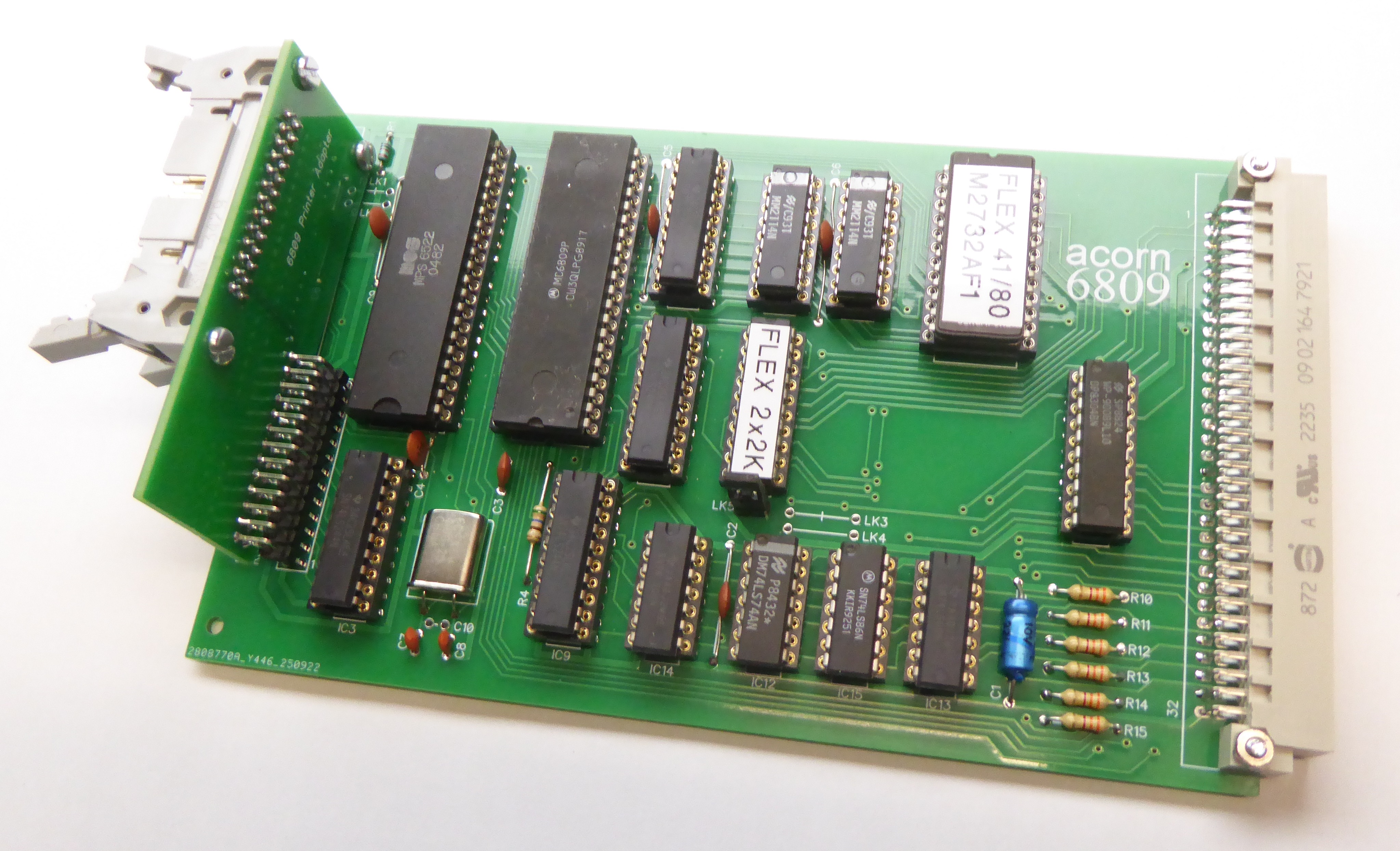
I have created two replicas of the Acorn 6809 CPU Board: the first is a close copy of the original whilst the second has had the address decoder PROM replaced with a PAL.
Acorn's original board used a one-time programmable 74S470 PROM (256x8-bit) for address decoding, this part is now hard to source and is expensive whilst the electrically programmable PAL is easily available and inexpensive.
(I haven't actually built the original however I'm confident that its correct as it is almost identical to the PAL version.)
The PAL version can be used with an additional small Printer Adapter PCB to enable mounting of the printer socket on the front panel (requires a 2" wide panel).
Firmware
Acorn provided a 6809 Monitor program for the board (listed in the 6809 User Manual) which works with the 40-column Teletext VDU and ASCII keyboard it is capable of booting the 6809 FLEX Operating System from a floppy disk using the Floppy Disk Controller.
Unfortunately I haven't yet found a copy of Acorn's version of FLEX though I'm working on it !
I have created a version of the 6809 Monitor source which can be assembled to work with either the original 40-column Teletext VDU or the 80-column VDU, it is also possible to assemble the code to run in a different memory mapping more compatible with the 6809 FLEX Operating System.
Configuration Links
The original board has two pairs of links that allow selection of either a 2K 2716 or 4K 2732 EPROM for IC4. There are a pair of links connected to pin 21 of IC4 which tie the pin to either +5V for 2716 or A11 for 2732. A second pair of links are next to the address decode PROM IC11 which join pins 9 & 11 and 13 & 14, these should be open for 2716 and linked for a 2732. The default for the board is 2716, the IC4 pin 21 link will need to be cut for 2732.
The use of the 16V8 PAL simplifies things as any configuration changes are made in the PAL's logic. I have though fitted a link (LK5) to one of the PAL inputs that can be used to make configuration changes e.g. to switch between two 2K images.
Both versions of the board have further links which make changes to the keyboard and cassette interface, these are not numbered on the original so the LK numbers referred to only apply to my schematics. The keyboard Strobe line normally connects to the 6522 (IC2) CB1 input via LK1 but can be tracked to PB7 via LK2 if required. The cassette input is normally connected via LK3 to the 6522 PB7 input but can be tracked to PA7 via LK4.
Address Decoding
As mentioned above one of the issues with the original 6809 CPU board was its use of a one-time programmable PROM for address decoding, the hard to find 74S470, being one-time programmable doesnot it make very amenable to development either ! The PAL device on the other hand is easily reprogrammed (I use my TL866CS) and makes it easy to reconfigure the board.
I do not have an image for the original PROM address decoder, I could probably work it out but wouldn't want the blame of getting it wrong when somebody programs a chip !
I do though have a number of images for the PAL address decoder and if one of these doesn't do what you want then you should be able to modify one of the source files to suit.
I use Microchip's WINCUPL (WINCUPL II | Microchip Technology) to generate the PAL code.
Address Decoder PAL Files
There are two groups of address decode files, 'Monitor' are for the original Acorn Monitor configuration whilst FLEX rearrange the memory map to suit FLEX, details can be found on the 6809 Monitor page.
Monitor_2x2K allows for a 2732 EPROM to be fitted with two 2K images selectable via LK5 e.g. for 40 or 80-column Monitor versions:
Monitor_2or4K allows for switching between a 2K 2716 or 4K 2732 EPROM via LK5:
FLEX_2K configured for a 2716 EPROM for the FLEX memory map:
FLEX_2x2K the same as Monitor 2x2K but for the FLEX memory map:
Schematics
Here are the board schematics
Bill Of Materials
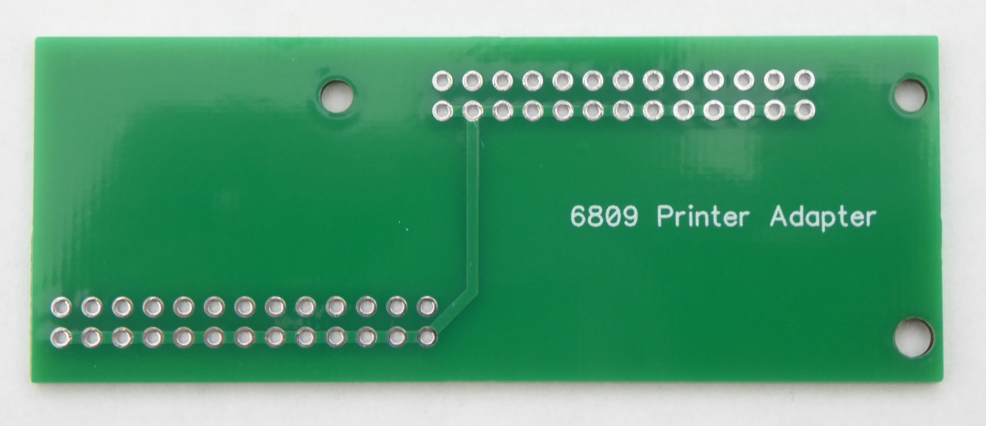
Printer Adapter
The Printer (PL2) connector is set back on the PCB rather than being on the edge of the board as in the 6502 CPU boards. In order to be able to mount a 3M type connector on a front panel I have made an adapter board that sits vertically on the main PCB.
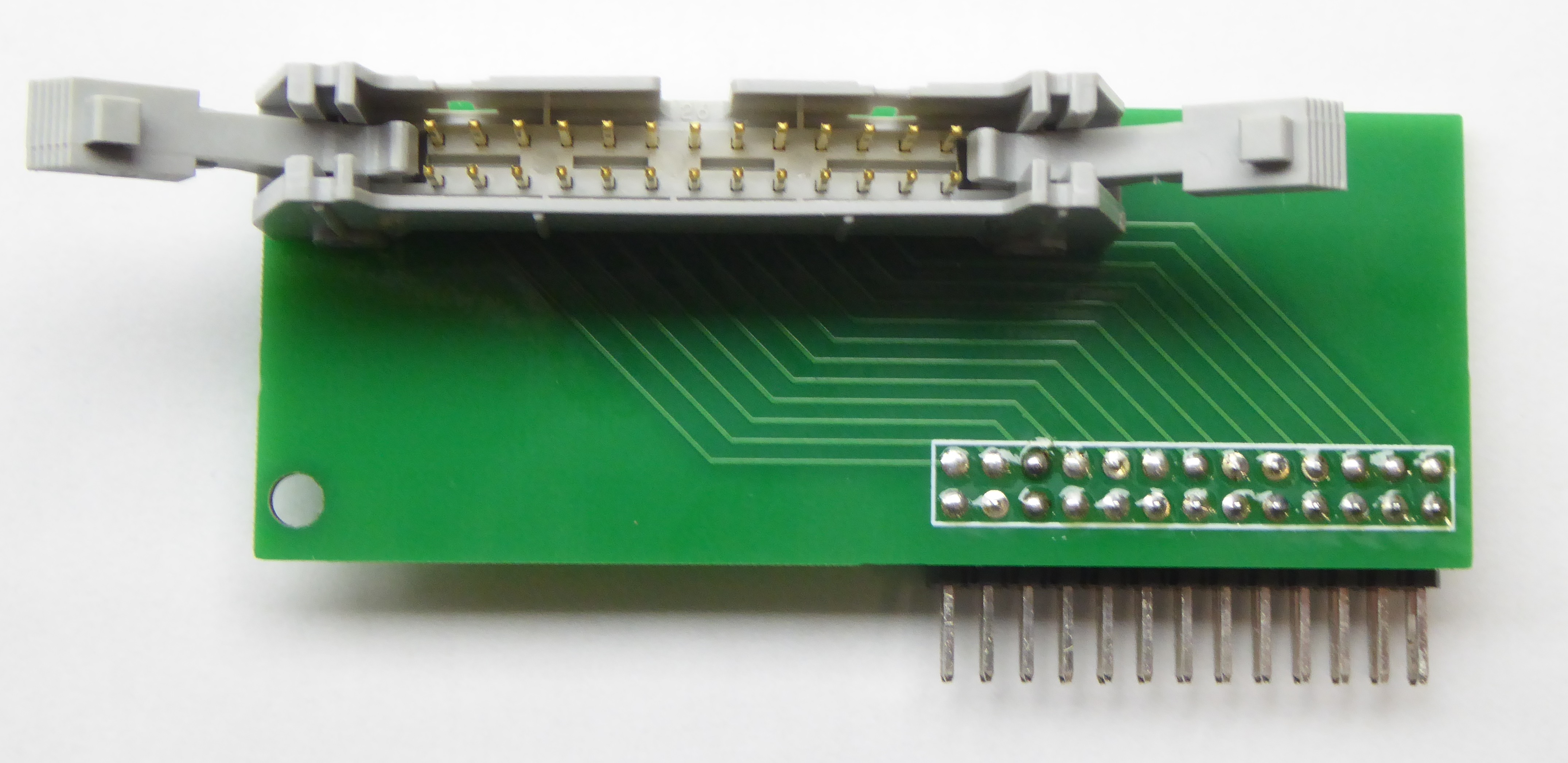
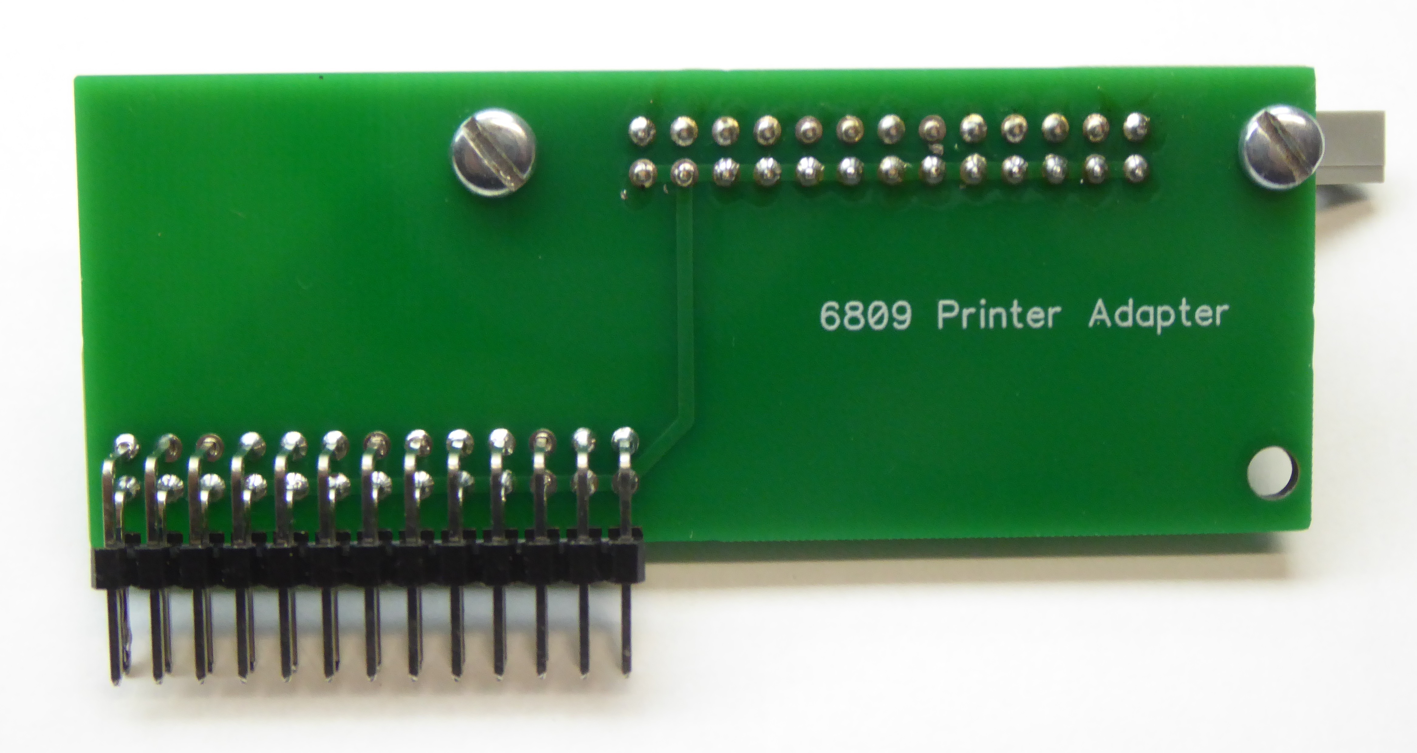
Its a little fiddly to build - attach the 3M connector first (solder and two screws) then loosely fit the right angle connector and fit the third screw to the keyboard connector PL1 (you will need to remove IC2 if fitted). Just solder one pin of the right angle connector to the main PCB and a couple of connections to the adapter PCB. Then dismantle it (remove screw from PL1 and desolder one connection), then solder the right angle connector to the adapter board and refit finally soldering the right angle connector to the main board.
(Note the adapter board doesn't quite fit to an original board as there is not sufficient clearance - I have moved PL2 slightly to the right on the 16V8 version.)
At some point I'll fit a front panel to mine and then I'll add the Front Panel Drawing.
Front Panel Drilling
6809 CPU Board Front Panel (to follow)
Blank PCBs
Original 74S470 based:
%20PCB.jpg)
Modified 16V8 based
%20PCB.jpg)